HuiZhou Superpower Technology Co.,Ltd.

bjin@sz-supower.com.cn

86--18820950101

Hem> Blogga> RBFPID-based Coordinated Master Control System for Fossil Power Units

RBFPID-based Coordinated Master Control System for Fossil Power Units

September 13, 2022
1Matlab/APROS Control Algorithm Verification Platform The MATLAB Toolbox is integrated in the Matlab7.0 or later version released by The MathWorks, USA. It is an OPC client data access software that provides a communication mechanism with the OPC server. APROS provides standard The OPC interface can be used as both an OPC client and an OPC server. It can be easily connected with other applications or external control devices with OPC standard interfaces to realize data interaction. This paper uses APROS as an OPC server and OPC client Matlab. Connect so that the OPC client can read and write various APROS internal variables.

With Matlab's OPC toolbox and APROS software's OPC server function, data communication between Matlab and APROS can be realized, thus building a Matlab/APROS verification platform.

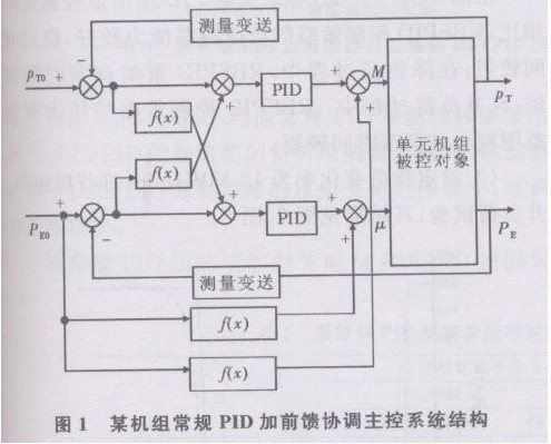
2 Control Structure The structure of the coordinated master control system equivalent to the logic configuration diagram of the coordinated control system of a unit is shown in Figure 1.

In Fig. 1, Pto and Peo are the main steam pressure and power set values ​​of the unit; Pt and Pe are the actual output of the system, ie the actual main steam pressure and actual power of the unit; u is the main steam control valve opening; M is the combustion rate.

RBFPID control system structure shown in Figure 2. In Fig. 2, the unit set is controlled by a double-variable coupling system (two input/output channels), and there is coupling between the channels. The control system is provided with two RBF neural network identifiers RBFIB and RBFIT in parallel. Two PID controllers, PIDB and P1DT, control the two output channels respectively. TDL1 and TDL2 delay the current sampling signal, Ym1(k) And Ym2(k) is the output of the RBF neural network identifier. TDL1 completes the data acquisition delay. The collected data is Uo, Mo, and PT. The collected data is input to RBFB. RBFB is adjusted by the difference between Ym1(k) and PT. W1(S) and W3(S) are identified to obtain the PIDB parameters online. Jacobian identification information required for self-tuning (Figure 3). Similarly, TDL2 completes the data acquisition delay, and the collected data is Uo, Mo, and PE. The collected data is input to RBFT. RBFT is adjusted by the difference between Ym1(k) and PE to identify w2(s) and w4(s). Gain the Jacobian identification information needed for on-line self-tuning of PIDT parameters.
3 Control Verification A 600MW unit simulation model was tested. The structure of RBFPID coordination master control system in Matlab environment is shown in Figure 4. Among them, RBFPIDB and RBFPIDT are main controllers on the boiler side and turbine side; OPCRead and OPCReadl are used to read the actual load and load set values; OPCRead2 and OPCRead3 are used to read the actual pressure and pressure setpoints; OPCRead4 and OPCRead6 are used Read the boiler side controller input and actual pressure; OPCRead5 and OPCRead7 are used to read the input and actual load of the turbine side controller; OPCWrite and OPCWritel send the control rate calculated by RBFPIDB and RBFPIDT back to the APROS model, and send it through the force point. The human virtual DCS makes RBFPIDB and RBFPIDT replace the virtual DCS Zhongyuan boiler and turbine main controller.

When the boiler and steam turbine main controllers are tested by RBFPID, it is necessary to set the feedforward control signal of the coordinating main control system as a constant value.

(1) Set the load change rate to 6MW/min. Use the original conventional PID plus feedforward control strategy and RBFPID control strategy to perform the unit load drop test. The results are shown in Figure 5 and Figure 6.


From Fig. 5 and Fig. 6, it can be seen that compared with the original conventional PID plus feedforward control strategy, the RBFPID control strategy has a better load tracking capability and a shorter stabilization time; in the process of load shedding, the RBFP1D strategy has a shorter seasoning time; During the ramp-up load process, the pressure change range of the RBFPID control strategy is smaller and the adjustment time is shorter.

(2) Set a load change rate of 12 MW/min, and perform a unit load drop test. The results are shown in Figure 7 and Figure 8.


From Fig. 7 and Fig. 8, it can be seen that compared with the original conventional PID plus feedforward control strategy, the load following ability of the RBFPID control strategy is better; during the test process, the pressure variation range of the RBFPID control strategy is smaller and the adjustment speed is faster .

The comparison of the control effects of the original conventional PID plus feedforward control strategy and RBFPID control strategy is shown in Table 1. When the load change rate is increased from 6MW/min to 12MW/min, the control effect of the original conventional PID plus feedforward control strategy is obviously worse, and the load following ability of the RBFPID control strategy is obviously better than the original conventional P1D plus feedforward control strategy. .
Kontakta oss

Author:

Mr. kevin kim

Phone/WhatsApp:

+8618820950101

populära produkter
You may also like
Related Categories

E-posta denna leverantör

Ämne:
E-post:
Meddelande:

Your message must be betwwen 20-8000 characters

Hem

Product

Phone

Om oss

Förfrågan

We will contact you immediately

Fill in more information so that we can get in touch with you faster

Privacy statement: Your privacy is very important to Us. Our company promises not to disclose your personal information to any external company with out your explicit permission.

Skicka